Rectifier Wiring Diagram With Alternator

Kohler Engine Electrical Diagram Kohler Engine Parts Diagram

Perfect Ford Alternator Wiring Diagram Internal Regulator Starter

192 Best Motorcycle Diagram Images Motorcycle Diagram
Connect to lighting leads from stator.

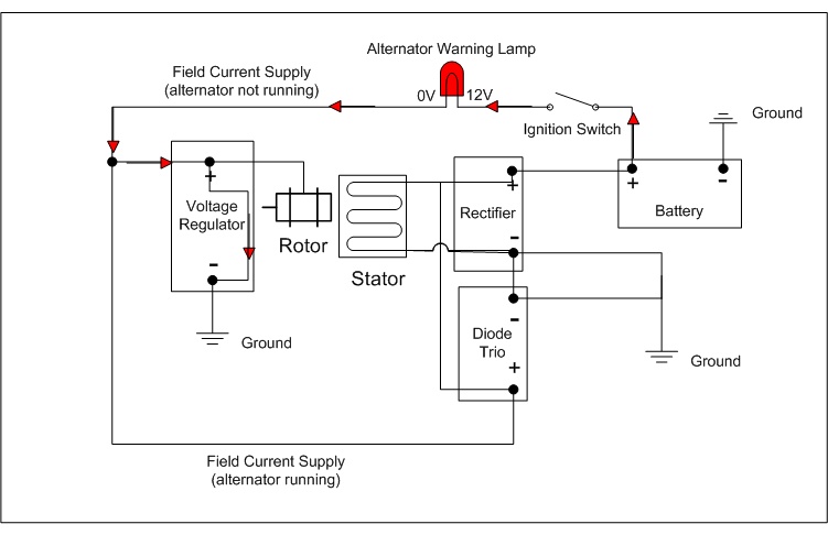
Rectifier wiring diagram with alternator. Diodes are like one way check valves that allow current to flow in only one direction. How to test an alternator testing the voltage regulator diode rectifier and stator duration. One wire alternator warning light duration. Connect to positive battery terminal and.
Need to see what alternator and voltage regulator it was setup with. Trail tech regulatorrectifier 7003 rr150 2 yellow wires. Regulatorrectifier 7003 rr150 tech support. Its supposed to assist all the typical user in developing a suitable method.
Trail tech stators have yellow lighting leads. A rectifier bridge can contain 3 6 or sometimes 8 diodes depending on its design. Alternator basics tips tricks 1 wire models of gm ford mopar from 1960 1980s autorestomod episo duration. Wiring diagram cen n1509 and n1511 dual voltage alternator description and operation n1509 and n1511 100 a 28 14 v dual voltage alternators are internally rectified.
Energize switch commonly an oil pressure switch activates regulator. American autowire 73130 views. Read through this briggs and stratton faq to find the electrical schematic or wiring diagram for your small engine. It didnt take too long until i had the potting thin enough.
Thought id see if i could remove the potting and see what was inside this baby. With this guide you may be able to determine how every component ought to. Alt wire diagram alternator wiring and out the dash warning light 12 volt alternator wiring diagram. Wiring diagram arrives with several easy to stick to wiring diagram directions.
This process is known. A positive biased diode allows only positive voltage to pass through and a negative bias diode allows only negative. These guidelines will likely be easy to grasp and apply. The bridges job is to convert ac voltage to dc voltage.
Field coil is then energized. Model of the ztr i just googled a wiring diagram and found this. Automotive alternator schematic diagram an automotive alternator is a three phase generator with a built in rectifier circuit consisting of six diodes.

10 Best Ac Generator Images Alternator Alternator Working

Pin On John Deere 757
Http Www Billavista Com Tech Articles Alternator Bible Images

Honda Spree Wiring Diagram Fitfathers Me Throughout Within

3 Phase Motorcycle Voltage Regulator Circuit Homemade Circuit

Hello I Have A Craftsman Riding Mower Modelnnn Nn Nnnnwith

Honda Wiring Diagram Diagram Electrical Wiring Diagram

1 Wire Alternator Wiring Diagram Diagram Alternator Wire

The Basic Distinction Is That Singly Excited System Have Magnet
